Physical Address
304 North Cardinal St.
Dorchester Center, MA 02124
Physical Address
304 North Cardinal St.
Dorchester Center, MA 02124
Learn how to streamline your CAD-to-Unity workflow using PiXYZ Studio and Blender. Step-by-step guide for optimizing meshes, reducing draw calls, and exporting clean models for XR projects.
In my last post, I took PiXYZ Studio for a spin. This time, I’ve finally landed on a reliable workflow for getting heavy CAD files into Unity — clean, optimised, and ready for XR use.
After some trial and error, I’ve built a repeatable process that gets CAD models cleanly from PiXYZ into Unity — optimised enough for real-time use but still looking good up close.
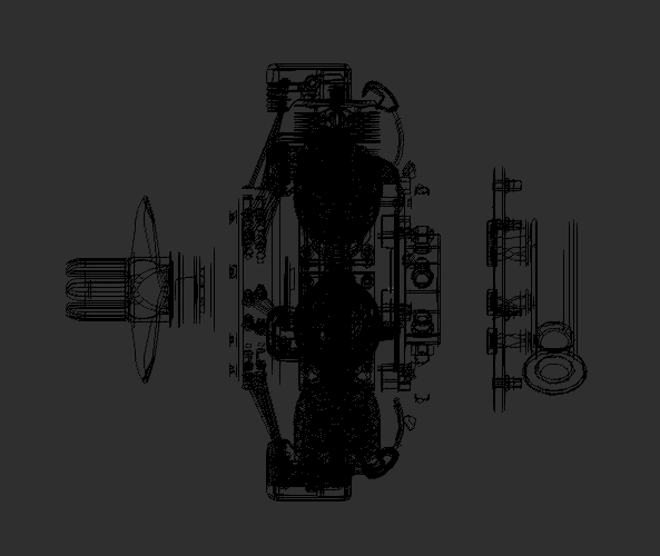
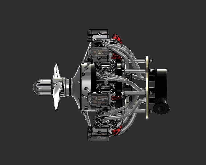
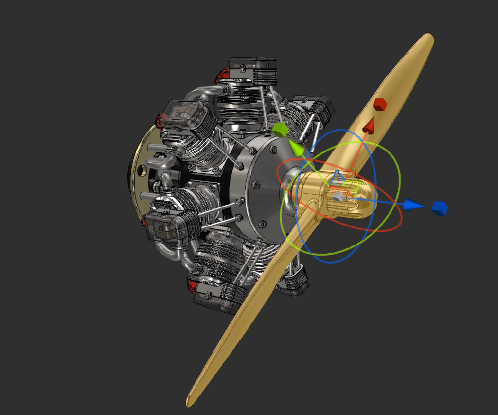
Everything starts here: a clean import sets the tone for every fix that follows.
I’ll skim this part since I covered it in my previous post. I took the inventor assembly file I was provided with and RAW imported it into PiXYZ. From there, I repaired CAD, Tessellated to medium settings, repaired Mesh, identified patches, repaired any holes, and finally removed any occluded part (unless the model is intended for an exploded view). The result is below:
Once the CAD model is imported, it’s almost always overbuilt for real-time use. The goal here is to trim mesh complexity without breaking what makes it look engineered.
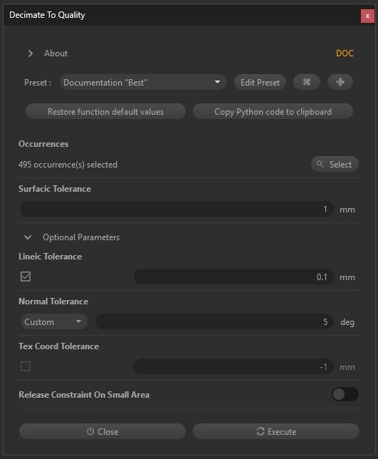
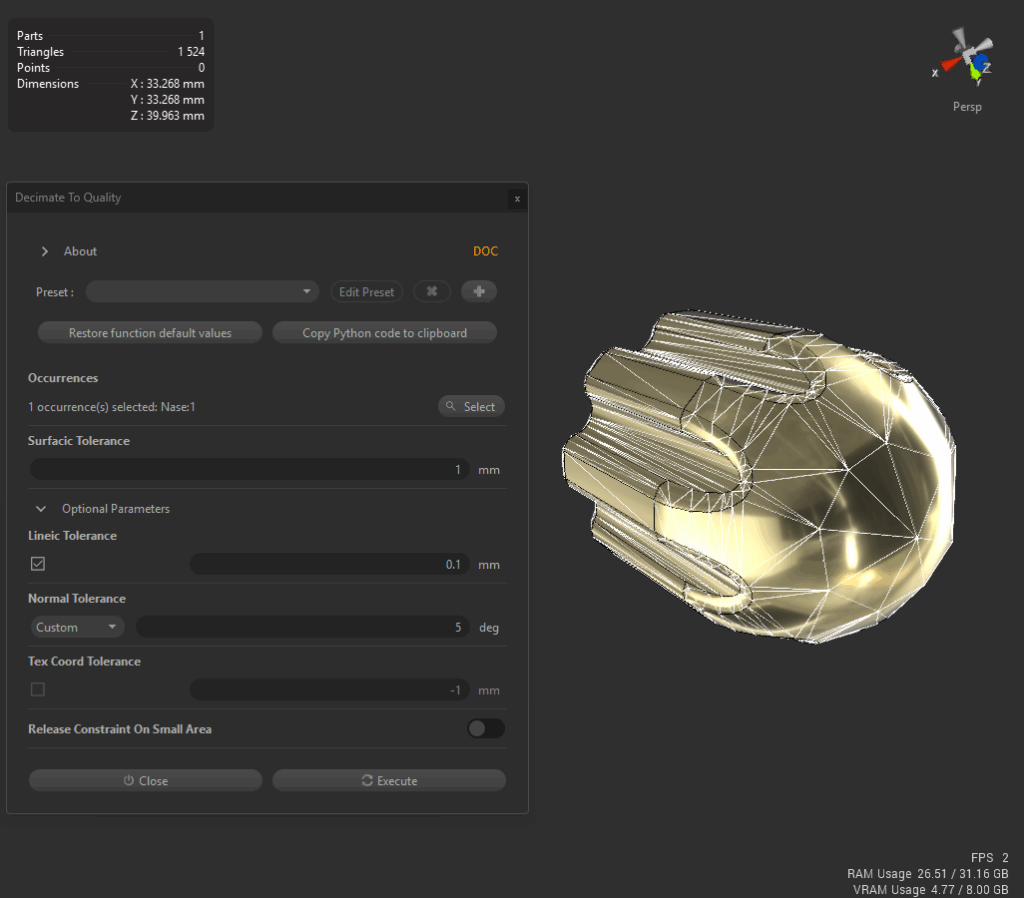
I start with PiXYZ’s Decimate to Quality tool using documentation presets (see screenshot).
This first pass took the model from 201 k to 185 k triangles—an 8 % reduction—without visible loss. It’s a quick way to verify that surface tolerances are reasonable before pushing further.
Next, I use Decimate to Target to step the polycount down gradually.
Wide curves and housings tolerate heavy reduction; thin edges or fillets don’t.
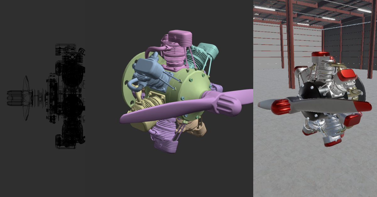
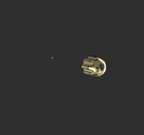
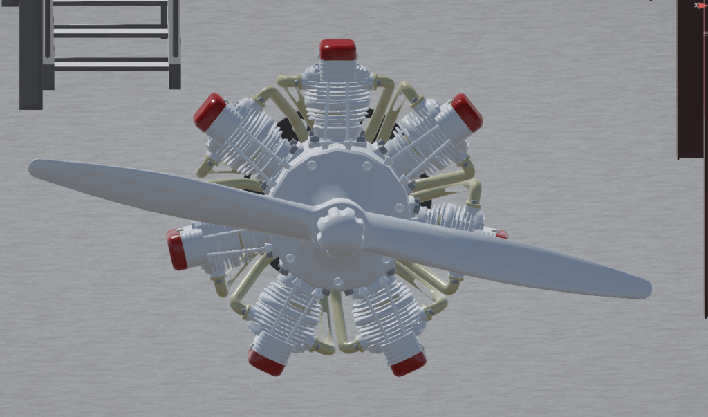
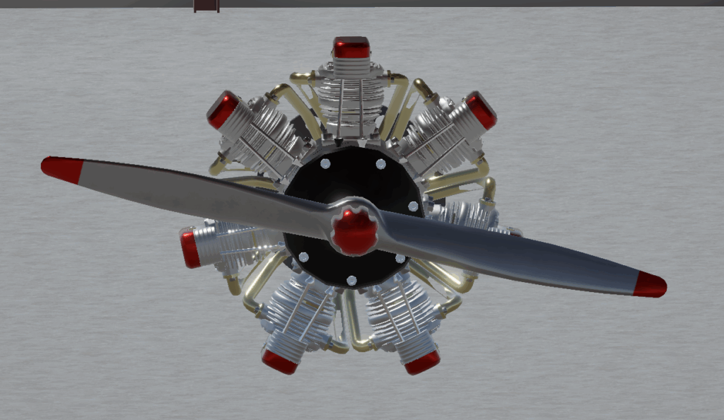
The before-and-after images show how geometry density affects the nose-cone detail.
This iterative decimation process taught me where PiXYZ’s automation works and where human judgment still wins.

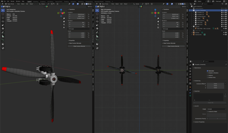
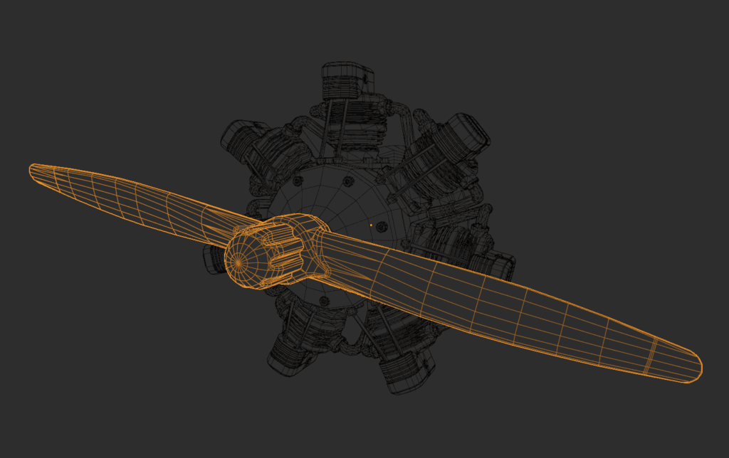
Highly detailed components—like this cylinder assembly—react badly to blanket decimation.
Surface warping and shading artefacts become obvious.
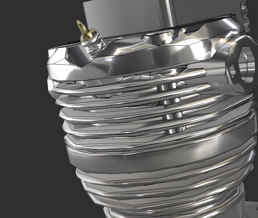
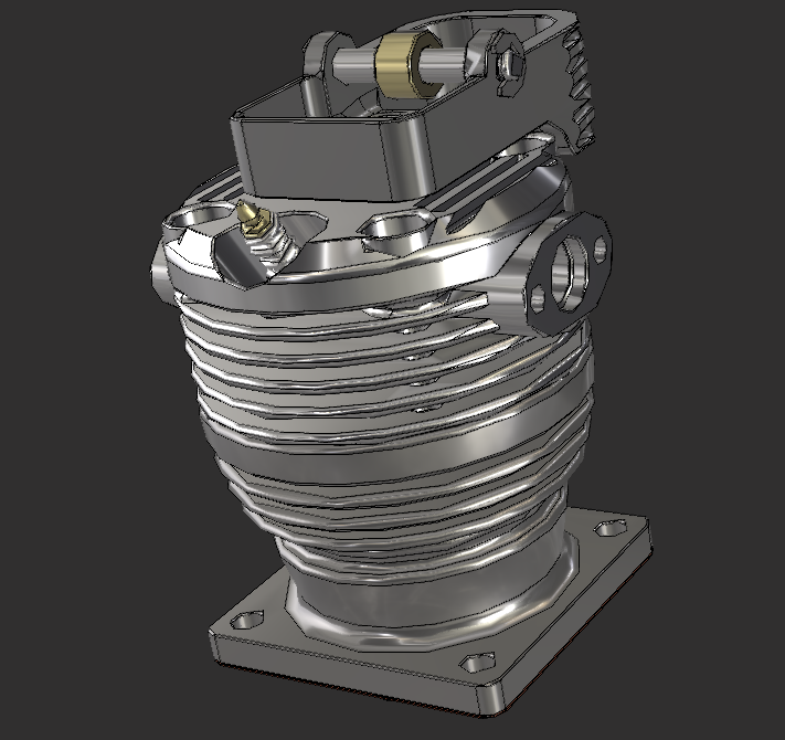
My fix: re-tessellate those parts at higher quality, then decimate them separately.
That preserved curvature while dropping tri-count from 11 k to 8 k, a 27 % cut with no visible hit at typical 1–2 m VR distance.
Where automatic tools still fail—such as tight pipe bends with distorted topology—I export those sections to Blender for manual clean-up.
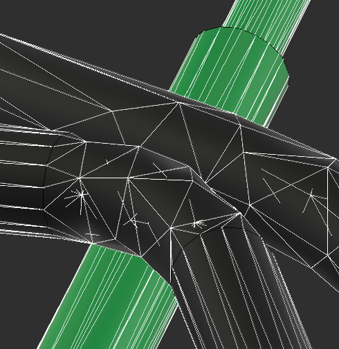
It’s faster than fighting bad geometry inside PiXYZ.
After optimising each group, I merge static sections together. This model went from 204 parts to 4, eliminating 200 draw calls.
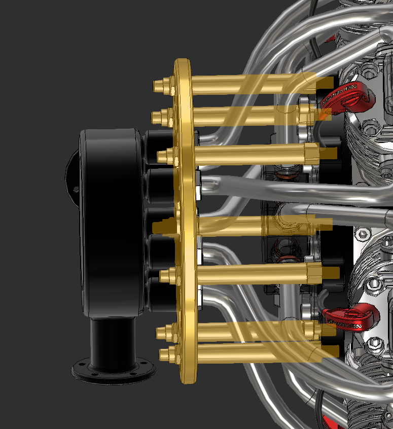
Doing merges last gives fine control earlier and better runtime performance later.
PiXYZ handles bulk optimisation, but Blender gives me surgical control over details.
Export from PiXYZ is a relatively easy process. Once optimised and merged to the required level, I can then export and save by adding the file format extension best suited for the context. For going to Blender, I usually go with FBX at this stage.
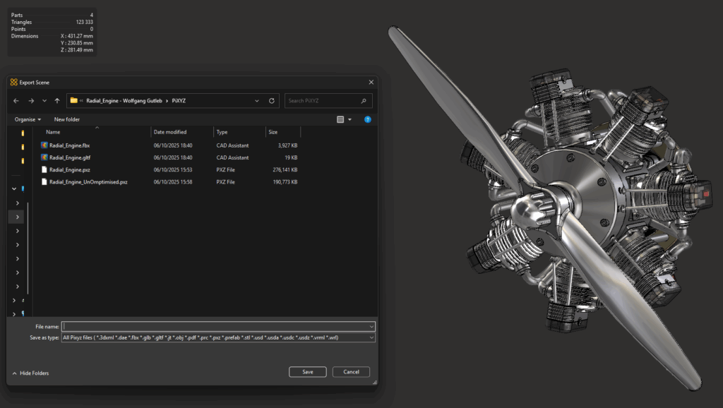
To help, I have listed the best use cases for each option in PiXYZ.
| Format | Best Use Case / Notes |
|---|---|
| 3DXML | Native Dassault Systèmes format; great for importing CATIA/SolidWorks assemblies. |
| DAE (COLLADA) | Useful for older tools or DCC apps; includes materials but can struggle with complex models. |
| FBX | Most common for Blender, Unity, and Unreal. Keeps hierarchy, scale, and materials intact. |
| GLB / GLTF | Best for 3D printing; single mesh, no colour or materials. |
| JT | Used in manufacturing workflows. Lightweight CAD data; not suited for real-time engines. |
| OBJ | Simple and universal; geometry only (no hierarchy or materials). Great for static models. |
| Embeds interactive 3D in a document for sharing or reviews. | |
| PRC | Engineering-focused; precise data used inside PDFs or CAD archives. |
| PXZ | Best for 3D printing; single mesh, no colour or materials. |
| Prefab | Unity export that creates ready-to-use prefabs directly from PiXYZ. |
| STL | Best for 3D printing; single mesh, no color or materials. |
| USD / USDA / USDC / USDZ | Pixar’s modern interchange format; ideal for complex pipelines or AR apps. |
| VRML | Legacy web 3D format; rarely used today except for archival purposes. |
Now that the heavy lifting is done, Blender helps clean up shading, fix normals, and merge smartly.
For this, I just do a standard FBX import into Blender. I’m currently using the latest LTS version 4.5.3. This step should really be minimal, as PiXYZ has done all the heavy lifting for us. Blender’s great for those smaller, fussy fixes that PiXYZ doesn’t quite nail — things like simplifying overcomplicated geometry or repairing shading oddities.
Let’s start with the most common one I run into: remodelling.
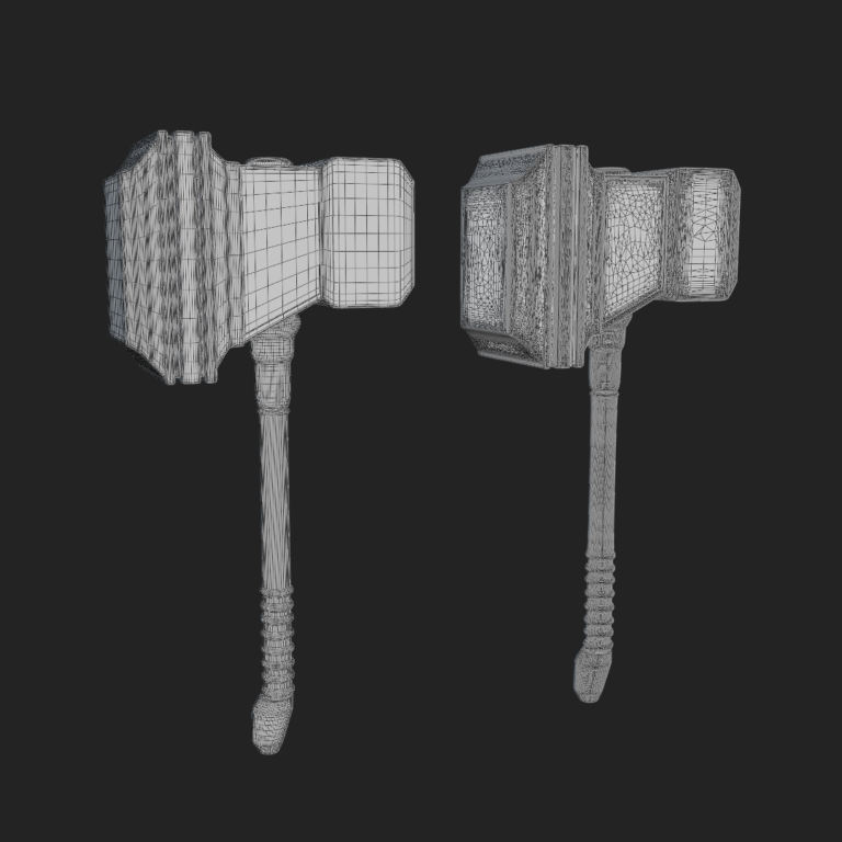
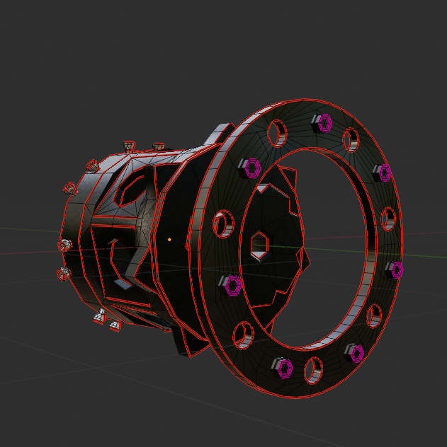
One of the downsides of mesh decimation and other optimisation techniques is that they’re not always perfect. They can overcomplicate geometry and produce dodgy UVs. In cases of objects like below, a simple cylinder with some holes in it, I have found that the results of optimisation can lead to surface artefacts, weird normals and a polycount that doesn’t justify the mesh complexity.
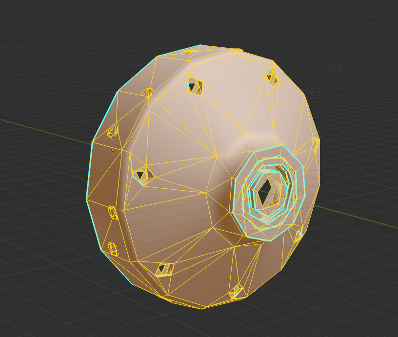

So in cases like that, I import the model into Blender and rebuild the part as closely as possible to the original. So far, this has produced better results for me than just using the output from PiXYZ. With the example shown, I made a few decisions based on the intended use, because this part of the model will remain static and won’t be interacted with, I decided to remove the holes for the bolts and have them intersect the mesh. This massively simplified the mesh, reduced polycount and made for a much easier UV unwrap. The plus side is that it will have no negative effect downstream in the game engine, and if the use case changes and the bolts somehow become important (unlikely…), the topology is now very easy to adapt.
The way I choose whether or not to remodel or just adjust a mesh is by asking myself a couple of questions:
The answers to these questions will come with experience, and sometimes I may get them wrong, but it is good practice to keep them in mind.
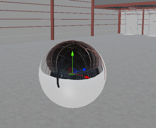
Once the geometry feels solid, the next issue usually shows up in the shading. Even with clean topology, odd reflections or dark patches can appear. That’s where Normal adjustments come in.
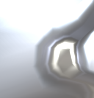
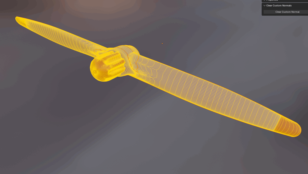
A fairly simple one, I often find that models have weird surface artefacts, and no amount of topology fixes seems to help. That is where the wonderfully annoying world of custom normals comes in.
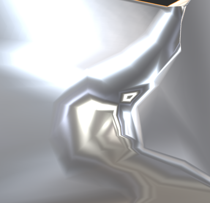
The screenshot above shows how decimation created odd warping and reflections, especially around the inner edge.. I have found an add-on for Blender specifically (link here) that removes them at the press of a button. For those who don’t want to use an addon, strange but your prerogative, go to Object > Data > Geometry Data > Remove split normal data. This should have the same results, but personally I think the addon is worth the £0 it costs…
With the surfaces cleaned up and behaving properly, I’ll usually do one last bit of prep work before heading to Unity — merging related parts.
Lastly is the merging of parts. It is possible to do this in PiXYZ, but I have found that doing it at this stage makes the above adjustments and UV unwrapping, etc, much easier. My method for merging parts is fairly simple. Below are some questions I ask myself when merging:
It’s easy to get carried away merging things too soon, but this rule keeps me from overdoing it.
Only merge what won’t need to move, be interacted with, or be reused separately later.
Once the meshes behave and the shading isn’t fighting me anymore, I move on to texturing — the fun part where it all starts looking less like CAD and more like something I actually want to see in a scene.
Texturing is where the model starts to feel like an asset instead of a CAD object. In this step, I’ll walk through my method for UVs, baking, and optimisation trade-offs.
Texturing is another area that can save a lot of performance if done efficiently, so I have outlined below a general version of each of my steps and decisions in the process. The actual process itself is very simple, but it requires some technical knowledge and creativity. That is why I will probably do another post solely focused on texturing, and for now, I will just outline the process and some of my decision-making.
A step that I can confidently say only sadists enjoy. It’s a simple task, put seams in the right places so they can’t be seen and cause as little stretch as possible. However, it is also an incredibly time-hungry step and going it without a plan of attack always increases that time.
Separate the model into its respective parts, ensuring that repeated parts, such as bolts or injector heads, are kept distinct so that they can be instanced in Unity.
I will then go through and unwrap each part, copying the UV maps of repeated meshes where I can, and then merging them into larger joint meshes afterwards for the purpose of atlas textures.
For VR use, especially but generally for most assets I work with, I use the high-to-low poly technique. This means baking from a high-poly version of the assets and then applying those textures to the low-poly assets to gain performance-free details.
To create the high-poly asset, I take the UV-unwrapped meshes and subdivide them so that they still share the same UV map for baked textures.
When I found out a little while ago that it was possible to bake procedural textures and image textures into Atlas maps in Blender, I don’t think I need to explain how excited this little nerd was. With the industry standard Adobe Substance Painter costing £48/month, finding a cheap/free alternative means I can continue to practice and learn.
So let’s have a look at how the process works, shall we?

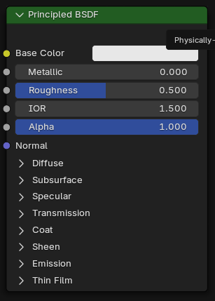
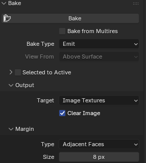
For settings, I make sure to select diffuse as the bake type, disable Direct and Indirect lighting contributions (so none of the scene lights are included in the texture), and set the margin size to 8px.
I have also found that setting the max samples in the render settings to 10 will significantly speed up the bake time without really affecting the quality of the maps.
I also found out after a lot of angry googling and countless YouTube videos that to get the colour to output properly, you have to set the metallic property of the materials to 0; otherwise, the bake will just output a black texture.
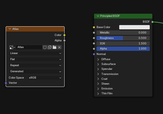
The next step is to create a new blank image. I tend to set this as a 2048px texture for performance concerns. Once this is done, add an image texture node, with this newly created image set as the target, to all the materials that will be included in the bake.
From here, make sure the model whose materials are being baked is selected, the image texture is the active node in all selected materials, and hit the bake button in the bake tab.
Once baked, I save the output locally; otherwise, I found out the hard way that you lose all the baked textures and have to do it ALL again. For all other textures, except metallic, which I will explain why in a moment, the process remains the same, just remember to select the right setting in the bake tab and change the image texture from sRGB to Non-Color.
Metallic is a weird one. There is no specific option in the bake settings for metallic, so it is output as an emission map. The rest of the changes to the process are pretty simple.
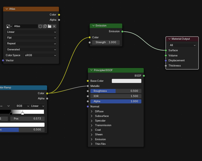
In the material, connect the last node in the metallic setup to an Emission node and connect that to the Material Output. If the Metallic input is just a number instead, connect an RGB node set to pure white to the Emission node.
The only real difference after this is to select ‘Emit’ in the bake settings. Again, ensure the image texture is set to Non-Color.
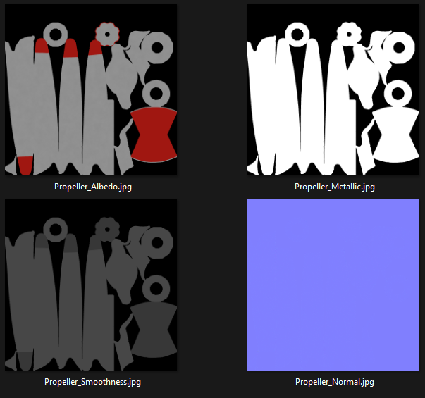
The screenshot below is an example of what the output bakes should look like..
Like I mentioned before, texturing is an area that can save a lot in performance downstream, but it isn’t always directly; it can be the reason performance is saved.
To demonstrate what I mean, look at the two diffuse textures below taken from polyhaven, and be honest, can you tell which one is the 2K and which one is the 4K texture? The only reason I know is because I’m the one who put them there. This is why stepping down in quality could save performance space, which could be used elsewhere, with very little visual cost.
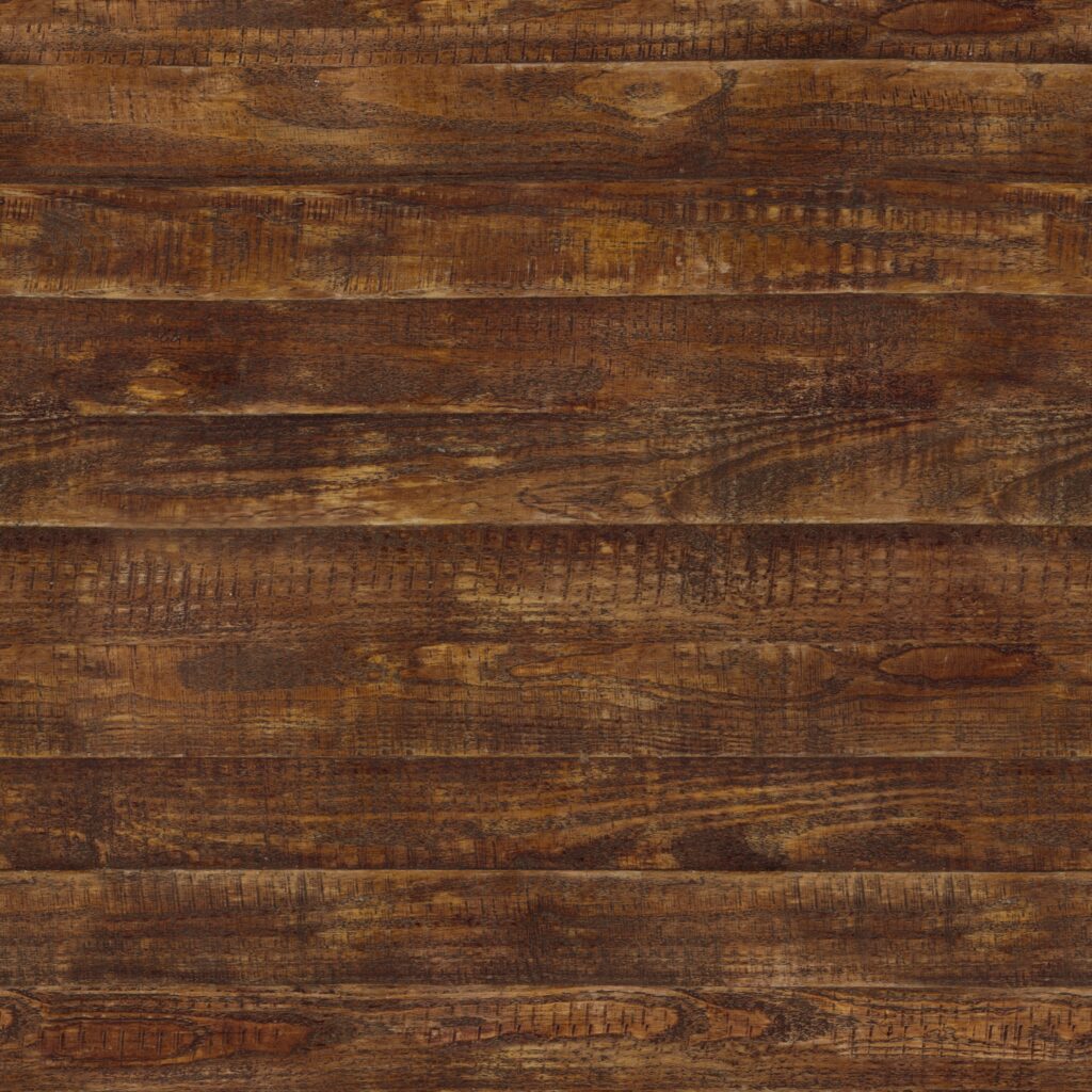
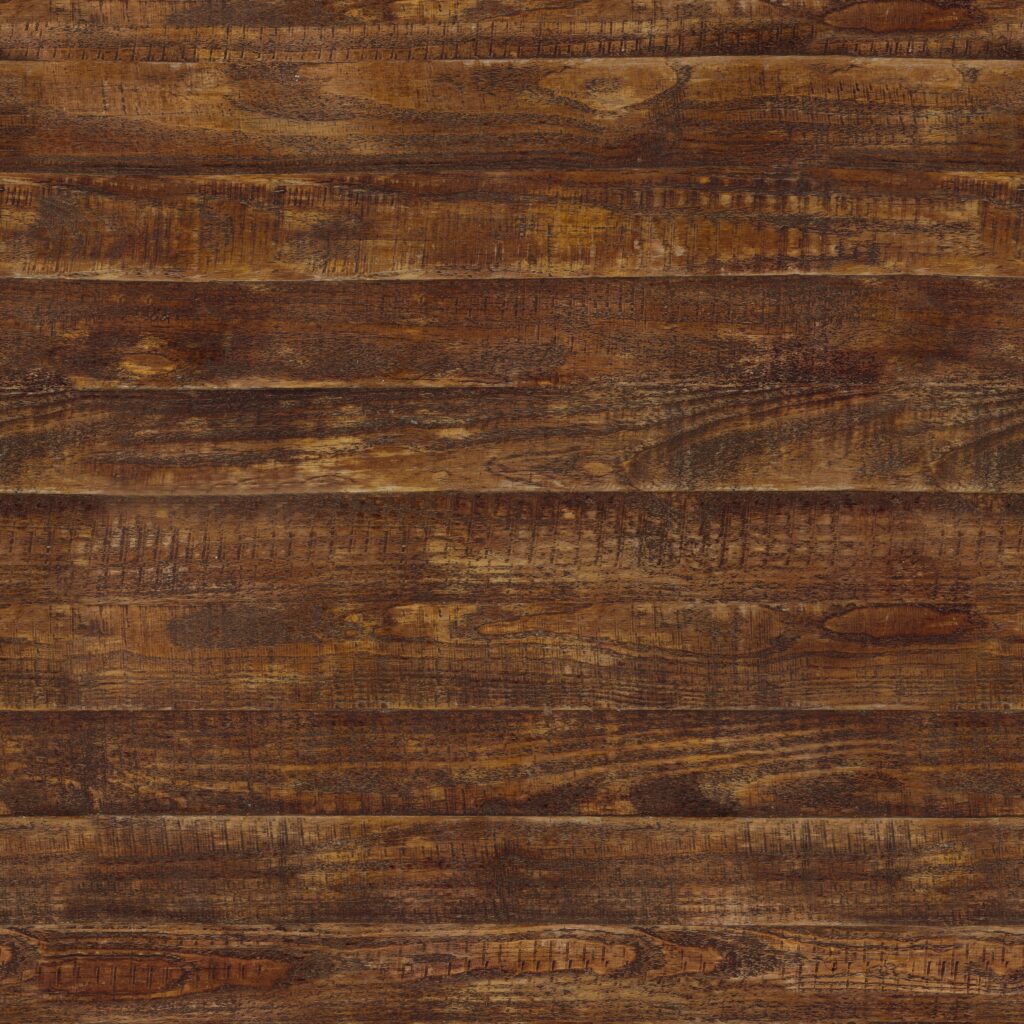
Textures themselves don’t cost much, only really costing in VRAM real estate. What costs in performance are high-poly assets, which is where baked textures really come into their own. Being able to bake the details from a high-poly asset and lay it over the top of low-poly makes a world of difference in the long run, as performance optimisation is all about saving lots of small pieces that add up.
So now that we have an optimised and textured model, let’s have a look at getting it into Unity.
With the model finished, Unity brings everything to life — this section covers my baseline XR setup and a few performance tweaks I’ve learned the hard way.
The model seen throughout this post is intended for a VR demo, so I will explain how I set up a project for that. Some of the settings and packages are different from if this were intended for PC, Web or Mobile platforms, but largely remain similar.
First thing to do is create a new Unity project. I did so using version 6000.0.58f2, as when I am writing this, it is the latest LTS.

Once Unity has taken its regular 5-6 business days to open for the first time, we have a few changes I would recommend doing at the start, just to keep a clean house. Also, make sure to fix any issues Unity shows on opening. For example, this time I got a deprecated package warning, which meant updating or removing the package.
Once I have the boring bit done and Unity has recomplied, restarted, recompiled again, imported assets, recompiled again, etc, etc. I move to package installation.
For VR projects, I have a little list of packages that are both required and/or useful to have in a project, so I start by getting those installed using the package manager. I will add the list below:
Packages:
- OpenXR
- XR interaction Toolkit (with Starter Assets)
- Meta XR All-in-One SDK (optional)
- glTFast
OpenXR is the open standard for VR and ensures compatibility across headsets, avoiding headset lock-in.
XR Interaction Toolkit provides locomotion, grabbing, teleportation, and default input bindings so you don’t have to go through the daunting process of writing these from scratch. Trust me, I attempted that for my master’s thesis, and it sucked…
Meta XR All-in-One SDK, if you don’t mind being locked into Meta and Meta alone, then the SDK is honestly great. It gives you building blocks that can be placed into the scene and tend to just work with each other. It also provides Meta-specific features like passthrough, anchors and better integration with Quest hardware.
glTFast provides functionality to import .glb/.gltf models efficiently while preserving their PBR materials. It supports drag-n-drop into the editor, where it will create a prefab and convert materials automatically. You can also use it to dynamically load external models at runtime, which I am looking forward to playing with.
It is at this point that I will go through the project and enable some of the key XR performance features to make sure I start off with the best possible baseline.
This will reduce the resolution in the peripheral vision to save GPU cost without a noticeable loss of quality.
By rendering both eyes in one pass, it cuts down on draw calls and almost halves the GPU cost compared to when using multipass.
I found this one when I was doing the locomotion thesis I mentioned before. It essentially reduces the head-tracking latency, resulting in a smoother and comfortable experience. A lot of the time, when users experience motion sickness, it can be as a result of this latency.
These settings are more what I would call “Quest friendly defaults”, so they are optional, but when testing with or designing for the Quest hardware, they can be useful.
Reducing the render resolution slightly can improve the frame rate with a minimal impact on visual quality.
The Quest doesn’t actually support temporal AA, so MSAA provides clean edges for VR comfort.
These settings will keep the shadows crisp nearby while resulting in less GPU load by reducing the quality over the specified distance.
Realistically, HRDs cost a lot in performance, and in my opinion, the little benefits gained do not outweigh the cost.
Last but not least, this removes the overhead from features not visible in the scene.
Once the project is set up correctly, we can go about adding all the assets we need for a project like this.
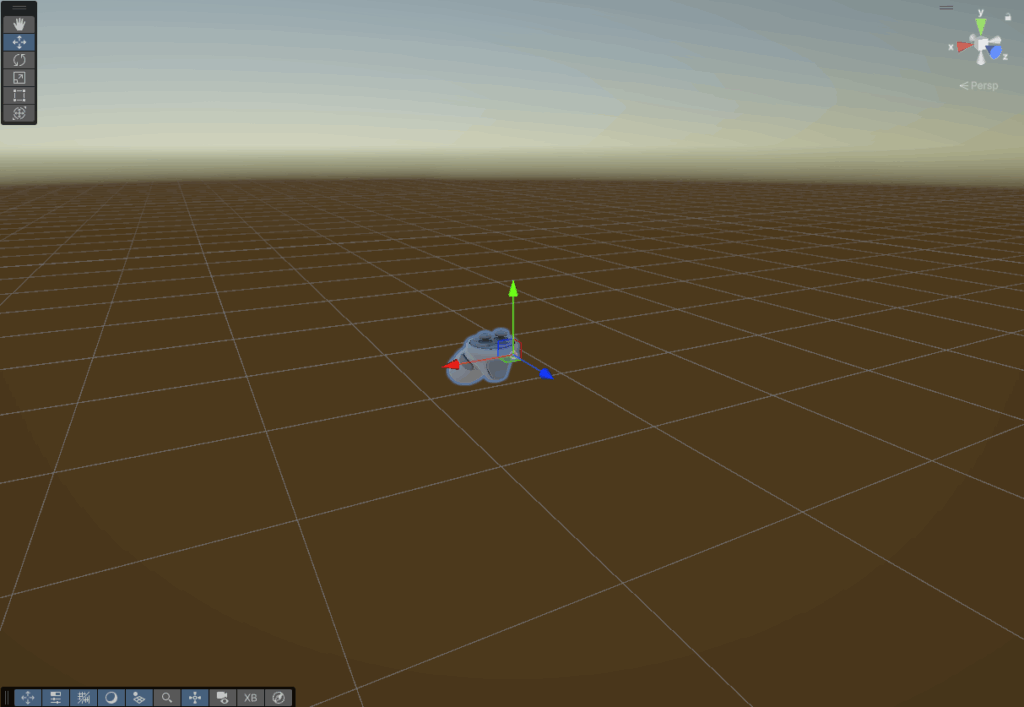
I like to add the XR Origin prefab from the XR interaction toolkit starter assets and put that in the centre of the scene for the moment. That way, I know where to build out from, the player has a camera to see through, and the inputs are all mapped.
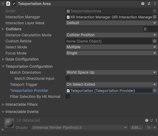
We have a rig, but they can’t move, so next to enter the scene is the XR interaction manager, the Locomotion system, and the teleportation provider. Which will automatically handle the logic.

Next would be to add the environment models intended for the scene. For the purposes of this project.
Lastly, adding in a directional light and reflection probes to provide realistic PBR lighting with minimal impact on performance.
Importing assets into Unity is very simple, and there is more than one method. One is to drag and drop the file(s) into the editor, and the other is to right-click in the project files and click ‘Import New Asset…‘, which will let you select the files or folder you want to import.
After importing, I drag and drop the model into the scene. From there, I add the materials previously baked, make any that were better suited to be made in Unity, like glass for example, animate and more, but in the interest of keeping this post from taking hours to read, I will stop here and pick this back up in another post that focuses on the processes and workflows i use inside of Unity.
This workflow has grown out of trial, error, and the occasional “why is this 4 million tris?” panic. It’s not perfect, but it’s reliable and keeps the look while staying performant for XR. I’m sure there are better ways—feel free to send them. That’s the point of this blog: to make sense of what I’m learning.
Next time, I’ll dig into Unity materials, lighting, interaction, performance profiling, and more.